NEW SPRAY TECHNOLOGY DELIVERS VARIABLE RATE APPLICATION WITHOUT A CHANGE IN DROPLET SIZE
| Date: 16 Sep 2009
Applicator needs for effective agricultural spraying
Successful spray application of agricultural chemicals is a balance between achieving the good coverage required for efficacy, reducing the occurrence of drift and keeping the operation as time and equipment efficient as possible. Good coverage is achieved through proper droplet size and placement, with advantages from smaller droplet sizes. Conversely, drift mitigation is often achieved through larger droplet sizes and often, higher spray volumes. Optimal efficiency is reached through higher ground speeds and lower spray volumes.
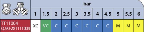
Spraying is also a very dynamic process. Variation in field conditions, shapes and obstructions can result in wide ranges of sprayer ground speeds. There is a trend toward increasing use of variable rate applications. Variable rate application requires changes in nozzle flow rates as the sprayer traverses through different rate zones. Conventional rate controllers, installed on conventional sprayers, can easily handle combinations of rate and speed ranges of up to 3-to-1; the limiting factor is usually the spray nozzle or the spray pump. A 3-to-1 rate range requires a 9-to-1 range in spray pressure. This 9-to-1 range is often beyond the capability of the pump. Furthermore, with conventional spray nozzles, changing the pressure over a 9-to-one range changes the droplet size. For example, consider a Turbo TeeJet�� 11004 fan nozzle, as the pressure is increased from 1 to 6 bar (representing only a limited 2.4 -to-1 change in nozzle flowrate), the droplet size classification changes from Extra Coarse to Very Coarse to Coarse to Medium, crossing four droplet size classifications (Figure 1). This variation could result in effects ranging from poor coverage and efficacy to increased spray drift.
Figure 1. Droplet size classifications across an operating pressure range for an example nozzle (Turbo TeeJet�� 11004 data adapted from Spraying Systems Catalogue No. 50).
Concept and advantages of Pulse Width Modulated Spraying
As shown above, pressure is used for spray rate control, even over a limited range, droplet size and pattern are affected. An alternative method is to use Pulse Width Modulated (PWM) spraying to avoid these effects. In PWM spraying, each nozzle is equipped with a small, fast acting solenoid valve that pulses at a rate of 10 Hz (pulses per second). The duration of each pulse is controlled so that the flow rate of liquid through the nozzle can be varied over a 10-to-1 range while the nozzle operates at a constant pressure or to produce a range of droplet sizes at a constant flowrate (Figure 2). This allows a wide range of flowrates to be used while maintaining droplet size and spray pattern. Uniform coverage is maintained, even though the spray is pulsing, by alternating the pulse timing of adjacent nozzles so that the pulsing is staggered across the boom. The system is designed to be compatible with existing rate controllers through a retrofit design. One version of the product uses a control module that interfaces between the rate controller and the flow control (pressure or servo valve) and adapts the pressure signal in order to change the pulse characteristics. Another version of the product runs independently of the rate controller and uses the pulsing to maintain a desired pressure regardless of application rate. 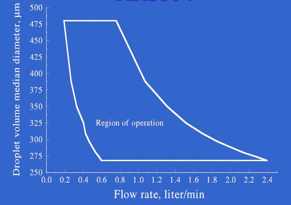
Figure 2. Flow rate and droplet size operation range for an 8004 nozzle under PWM spraying. Droplet size or flow rate or both can be adjusted through pulse and pressure control.
Examples of spraying in the field using PWM control.
In the first example, the performance of PWM spraying for maintaining a constant droplet size control across a range of vehicle speeds was demonstrated. Using a Case Patriot sprayer and mapping software, a transit was made “up and back” across a field. The sprayer speed was slow at the start, then speeded up in the centre of the field, slowed to make the turn at the edge and then speeded up again for the centre and then slowed at the edge. Across the speed range of 5 to 18 km/hr, the spray pressure was maintained in the range of 350 to 420 kPa and the droplet size and coverage remained constant as indicated by spray cards placed within the field (Figure 3). 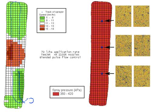
Figure 3. Spray pass up and back across a field with maps showing speed variation and spray pressure as the pass was made. Spray cards were placed within the field to indicate spray coverage.
In the second example, an additional capability of the system was demonstrated. The PWM spraying design can be used to allow a range of pressures to be used independently while operating over a range of speeds or application rates. A valuable way to use this capability is to adjust pressure and droplet size depending on wind conditions and proximity to spray sensitive areas. In this example, a weather station was mounted on the sprayer and supplied wind speed and direction to the operator. When the operator was near the north (top) end of the field, the spray pressure was decreased and the droplet size increased in order to compensate for the higher wind speeds coming from the south (bottom) end of the field (Figure 4). The PWM spraying system allowed the spray rate to remain the same throughout the application (Figure 5).
Conclusion
Pulse width modulation spraying allows a wider range of application rates and ground speeds to be used without compromising coverage or drift control. Variable rate application and real time drift control are two valuable uses for the technology. The technology has been in use for a number of seasons in the U.S. and is available from a number of vendors. 
Figure 4. On-board weather recorded during a single up and back spray pass across the N-S oriented field. Wind direction was primarily from the SW and speeds were highest at the north end of the field. 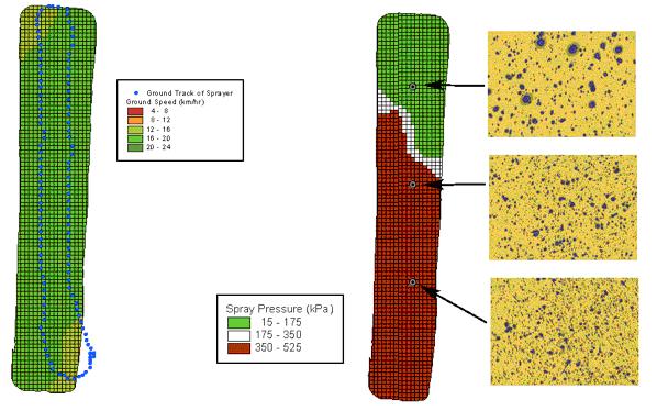
Figure 5. Active drift control during spraying of the field under the weather conditions in Figure 4. Rate and speed were maintained yet pressure was reduced to increase droplet size while spraying north end of field.
Contact details
Ken Giles
Department of Biological and Agricultural Engineering
University of California, Davis
Davis, CA 95616 USA
Phone +1 530 752 0687
Fax +1 530 752 2640
dkgiles@ucdavis.edu
Was this page helpful?
YOUR FEEDBACK